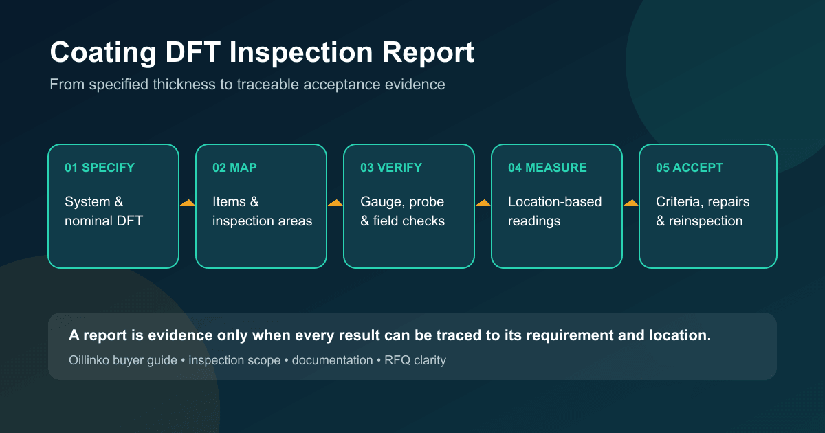
A dry-film thickness report can contain hundreds of readings and still fail to answer the buyer’s main question: does the applied coating comply with the approved system and the project’s acceptance basis? A spreadsheet of numbers is not self-explanatory. The reader needs to know what was coated, which layer or completed system was measured, where readings were taken, how the instrument was checked, which standard governed the sampling, and how the recorded results were judged.
Dry-film thickness, commonly shortened to DFT, is the thickness of a coating after it has dried or cured. It is an important quality-control measurement because inadequate thickness can reduce the intended barrier protection, while excessive thickness can also create coating-specific problems. Neither outcome can be assessed through a universal target. The approved coating system, product data, service environment, project specification and referenced inspection standard must establish the requirement.
Start with the coating system and governing document
The RFQ or inspection and test plan should identify the approved coating system, substrate, surface preparation, coat sequence, nominal dry-film thickness and any specified minimum or maximum. State whether acceptance applies to each coat, the total system, or both. A final total thickness cannot prove that every intermediate coat met its own requirement, so inspection stages must be agreed before later layers conceal earlier work.
Name the measurement standard and edition. ISO 19840 defines a procedure for verifying dry-film thickness against nominal thickness on rough surfaces, including instrument adjustment, inspection areas, sampling plans, measurement methods and acceptance or rejection criteria. AMPP describes SSPC-PA 2 as a standard for the frequency and acceptability of DFT measurements. These references should not be blended into a home-made rule without an approved project definition.
Identify the item and measurement boundary
A useful report identifies the project, purchase order, equipment tag, drawing or spool number, coating system, colour or product designation where relevant, and the date and stage of inspection. For assemblies, the report should explain whether readings cover the entire unit or selected components. Pipe, structural steel, vessels, skids and small fabricated parts have different geometries, so the inspection area and sampling plan should match the actual item.
Ask the supplier to mark measurement zones on a drawing, inspection map or clear item list. This matters when areas are repaired, inaccessible after assembly, exposed to different service, or coated with different systems. Recording only “acceptable” against a batch of items makes later investigation difficult. Traceable location references let the buyer connect an outlying value, repair and reinspection result to the same physical area.
Separate readings, spot measurements and area results
Do not assume every number in a report has the same meaning. A displayed gauge reading may be one observation. A spot measurement may be calculated from several readings, and an inspection-area result may combine several spots according to the named standard. The quotation and ITP should use the terminology of the governing document and state the required extent of inspection. Otherwise, two suppliers can claim the same number of tests while collecting very different evidence.
The report should preserve enough detail to review distribution as well as summary values. Minimum, maximum and average values can help, but they should not replace the underlying location-based results when those records are required. A high average does not automatically compensate for a locally thin area, and an isolated high reading may need review against a maximum limit defined for the coating system. Apply the specified acceptance logic rather than inventing a percentage rule after inspection.
Account for substrate and surface profile
Measurement method depends on the substrate and coating. Magnetic-induction instruments are commonly associated with nonmagnetic coatings on ferrous substrates, while eddy-current principles are used for suitable nonferrous substrates. The proposed gauge and probe must suit the base material, coating thickness range, curvature and access. Complex edges, welds and small diameters can require additional care or different probes.
Abrasive-blasted steel is not smooth. ISO explains that surface roughness influences the indicated value and addresses correction or adjustment methods for rough surfaces. The report should therefore identify the relevant surface profile approach and the method used, rather than presenting corrected values with no explanation. This is especially important when nominal thickness is close to the profile scale or when readings from different inspectors and instruments are being compared.
Record gauge control and field verification
A current calibration certificate is useful, but it is only one part of measurement control. The inspection record should identify the gauge, probe and serial number, the calibration or traceability evidence required by the quality plan, and the checks performed before and during use. It should state the reference foils, coated standards or zero plates used where applicable and describe any substrate-specific adjustment.
Elcometer’s DFT calibration guidance distinguishes controlled thickness standards such as foils, coated standards and zero test plates. Its separate guidance also notes the difference between formal calibration and the verification or adjustment performed by a user. Buyers should keep these terms clear. A report that lists a calibration date but omits the field verification does not demonstrate how the instrument was set up for the inspected surface.
Define acceptance, repair and reinspection
The purchase documents should say who evaluates results, what constitutes a nonconformance, and how repairs are proposed and approved. They should also identify the reinspection extent after repair. Recoating one marked location may affect adjacent areas, recoat compatibility and total film thickness. The coating manufacturer’s written requirements and the approved procedure should govern surface preparation, recoat windows and curing; a DFT article cannot safely replace those product-specific instructions.
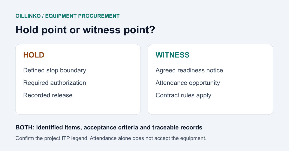
AMPP’s guidance on coating specifications and inspections emphasizes that thickness tolerances, inspection frequency and acceptance criteria vary with the system, standard and service environment. It also explains why inspection occurs at appropriate stages rather than only after final cure. The buyer should therefore agree witness points and documentation timing before coating begins. The ITP hold and witness point guide provides a framework for notification and release authority.
Request a complete DFT report package
A complete deliverable normally identifies the inspected items and zones, approved coating system, specified thickness, governing measurement standard and edition, instrument and probe, field checks, inspection date, ambient or surface information required by the project, individual or grouped results, acceptance decision, inspector identity, deviations, repair locations and reinspection results. Photographs and marked-up drawings can support traceability, but they should complement the numeric record rather than replace it.
Ask bidders to state whether DFT inspection, third-party witnessing, raw data export, calibrated-gauge evidence and final dossier compilation are included in the base price. If independent attendance is required, define its scope using the third-party inspection guide. Keep DFT separate from adhesion, holiday detection, surface cleanliness and other coating tests: each has a different method and acceptance purpose.
Turn the requirement into a comparable enquiry
Send Oillinko the equipment list, coating specification, approved system, drawings, nominal thickness requirements, measurement standard, inspection extent, ITP and required report format. Use the inspection and engineering enquiry page to describe the project and attach the controlled documents. Oillinko can route the request to suitable sources and coordinate clarification, while the purchaser and responsible engineering parties retain approval of the coating system, inspection method and acceptance criteria.
The best time to resolve reporting details is before coating starts. A concise, controlled requirement produces offers that can be compared on the same basis and records that remain useful at receiving, installation and later maintenance. It also prevents a long list of unlabeled readings from being mistaken for proof that the specified coating system was accepted.
Frequently asked questions
Is an average DFT value enough to accept a coated item?
Usually not. The governing project specification or measurement standard defines the inspection areas, number and grouping of readings, permitted local variation and any maximum limit. A single overall average can hide thin or excessively thick locations.
Does a gauge calibration certificate prove that the site readings are correct?
No. Calibration establishes the instrument’s relationship to a reference under stated conditions. The inspection record should also show suitable verification or adjustment for the substrate, probe and measurement range used during the work.
Can ISO 19840 and SSPC-PA 2 be combined in one acceptance rule?
Only when the project specification deliberately defines how. They are separate frameworks. The order should name the governing document and edition, then record any approved project-specific modifications without mixing terminology informally.